Incident Overview
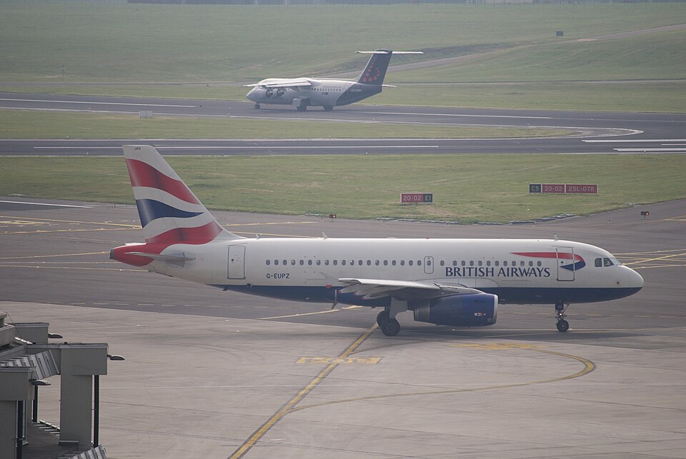
On 15 March 2009, at 1935 UTC, an Airbus A319-131 (registration G-EUPZ) operated by a commercial airline experienced a serious incident during engine start at London Heathrow Airport. The aircraft had 6 crew and 87 passengers on board; no injuries were reported.
Sequence of Events
After pushback at 1930 hrs, the co-pilot started engine No. 2 successfully, then commenced starting engine No. 1. As generator No. 1 was expected to come online, the commander's primary flight display (PFD) and navigation display (ND) blanked, the master caution aural warning sounded, cockpit overhead lights dimmed, and cabin lights dimmed. The Electronic Centralised Aircraft Monitoring (ECAM) system displayed faults: ac bus 1, fws fwc 1, and elec gen 1.
The crew performed ECAM drills, including placing the avionic cooling blower switch to override, and reset generator No. 1 by switching it off and on. Upon reset, a loud noise emanated from behind the right circuit breaker (CB) panel (behind the co-pilot's seat), accompanied by a slight smell of electrical burning. The co-pilot inspected the area with a torch; no smoke or tripped CBs were observed, though some CBs hidden by the sliding jump seat were not checked.
The commander declared a PAN and requested a tow back to stand. The co-pilot shut down both engines, after which the flight deck lights returned to normal brightness. The crew did not consider an emergency evacuation necessary and did not don oxygen masks. Passengers disembarked normally via the air bridge. After the aircraft returned to the parking stand, external electrical power was connected (not selected) and the APU generator remained running.
Damage and Investigation
Damage was limited to an overheat in the area behind flight deck panel 123VU. Investigation revealed evidence of significant electrical overheat behind the right CB panel. The exact initiation of the fault could not be fully established, but it was most likely due to a loose article. The presence of dust in the area was also considered a contributory factor.
Electrical System Context
The A319's AC electrical power is normally supplied by two engine-driven integrated drive generators (IDGs), each producing 115/200 VAC, 3-phase 400 Hz. The APU generator and external power can also supply the network. Each generator connects via a Generator Load Contactor (GLC). Bus Tie Contactors (BTC) allow cross-feeding. Differential Protection (DP) detects short circuits; a DP1 or DP2 can isolate faults. The crew can reset a generator fault twice; a third attempt is inhibited. Power from generator No. 1 upstream of GLC1 supplies fuel pumps during the 'Smoke' procedure.
Recorded data from the FDR, CVR, and QAR showed that after engine No. 2 started, engine No. 1 started, and shortly after, AC Bus 1 was lost. The generator No. 1 reset caused a CVR power interruption and loud interference on all channels.