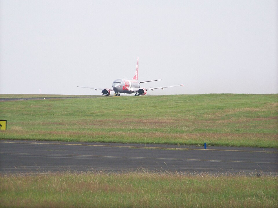
History of the Flight
The flight crew reported for duty at Leeds Bradford Airport at 0500 hrs for a 0600 hrs departure to Schiphol Airport, Amsterdam. Pre-flight preparations and engine starting proceeded normally, and the aircraft taxied for departure from Runway 14. The co-pilot was the Pilot Flying (PF), with the commander as the Pilot Monitoring (PM). The commander was the fleet training manager, experienced in abnormal checklist procedures in the simulator. A reduced-thrust takeoff was carried out with the auto-throttle (AT) engaged.
Shortly after lift-off, the commander heard a click and noticed the AT had disengaged. During the initial climb, the master caution and amber FLT CONT caption illuminated, indicating a failure of the Mach trim. At about the same time, the commander’s electronic attitude director indicator (EADI) and electronic horizontal situation indicator (EHSI) went blank, and his altimeter, vertical speed indicator, Mach ASI and radio altimeter failed with off flags showing. The No 1 Transformer Rectifier Unit circuit breaker tripped, and the commander attempted to reset it, but it tripped again. The flight management computer (FMC) failed, and both control display units (CDUs) locked up. The PF’s flight instruments and displays still functioned, but he was unable to display the departure track on his EHSI. The commander briefly confirmed the standby instruments were operating correctly by comparing them with the PF’s instruments.
After the landing gear and flaps had been retracted, the after-takeoff checks were completed. The climb was stopped at 4,000 ft. The commander used the DC and AC meter rotary selectors to check the electrical power system, which appeared normal other than a slightly higher indication on the No 2 generator. The flight crew decided to return to Leeds Bradford Airport. They identified that the yaw damper, left forward window overheat, a fuel pump, and normal exhaust fan were also inoperative. Additionally, the battery charger, electric hydraulic pump ‘B’, and normal exhaust fan circuit breakers had tripped.
The commander started the APU and called the Senior Cabin Crew (SCC) member to the flight deck, giving her a NITS briefing. She left and walked to the rear galley, noticing a distinct smell of electrical burning but no smoke. Her colleagues also mentioned the smell. The SCC alerted the flight deck and pulled circuit breakers to isolate the galley electrical systems. The commander transmitted a PAN call and requested an immediate return. He also selected the flight deck galley electrical power switch off.
ATC provided radar vectors for a visual approach to Runway 14, with the ILS set on the co-pilot’s instruments as backup. The weather was good. The commander re-briefed the SCC that they would land sooner, with no intention to evacuate but cabin crew to be at stations after landing. Without the FMC, the commander elected to use flap 40° and a VAPP of 140 kt. On final approach, the No 1 generator tripped offline. The cabin emergency lighting illuminated then extinguished. The commander selected the APU generator to generator bus 1, restoring his EADI, EHSI, analogue instruments, FMC, and CDUs. The FMC calculated VAPP as 127 kt. After an uneventful landing, the aircraft taxied clear, engines shut down, and passengers disembarked onto coaches; the aircraft was towed to a stand.
Recorded Data
The aircraft was fitted with a 25-hour FDR and a 30-minute CVR. The FDR recording stopped 4 seconds after lift-off and re-started 3 minutes 25 seconds before touchdown, as the FDR is powered by phase ‘A’ from the 115V AC generator bus 1, which was lost after takeoff and restored during approach. No electrical power system status parameters are recorded. Limited flight parameters were transmitted to ATC via Mode S transponder returns over 26 minutes 30 seconds. The CVR continued operating during the FDR power loss but also recorded after landing, and pertinent evidence was not preserved.
Aircraft Examination
Examination of the electrical system revealed that the red phase ‘A’ ground cable from the No 1 generator had separated from the T191 stud on the No 1 engine due to a failure of its terminal lug. Further inspection showed a cracked terminal lug on the blue phase ‘C’ ground cable at the T191 stud and another cracked lug at the firewall end of the grey ground cable. The crack on the blue phase ‘C’ lug was visible only after removing heatshrink insulation. The red phase ‘A’ cable had a tight bend radius within limits for a restricted area. The battery charger in the avionics bay smelled burnt; internal examination revealed a burnt coil connected in three-phase to the internal transformer. The following circuit breakers in the flight deck had tripped: Transformer Rectifier Unit No 1, Battery Charger, Electric Hydraulic Pump System B, and Normal Exhaust Fan Power. After replacing the No 1 generator harness and the battery charger, functional and flight tests revealed no faults or smell of electrical burning.
Probable Cause
Fatigue failure of the terminal lug on the end of the No 1 generator phase ‘A’ ground cable.