History of Flight
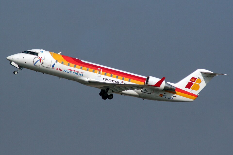
On February 28, 2009, at approximately 0840 EST, a Bombardier Aerospace CRJ-200, registration N830AS, was preparing for flight at Tallahassee Regional Airport (TLH) in Tallahassee, Florida. Shortly after external power was applied to the airplane, the flight attendant and captain heard an unusual hissing sound, which was quickly followed by smoke and signs of a fire. They immediately evacuated the airplane via the airstair without injury. They were the only individuals on board at the time. The fire department extinguished the fire, but not before it had burned a hole through the left upper cockpit crown skin. The airplane was registered to and operated by Atlantic Southeast Airlines as flight 5563 under 14 Code of Federal Regulations Part 21. The planned flight was from Tallahassee to Hartsfield Jackson Atlanta International Airport (ATL) in Atlanta, Georgia.
Injuries
Neither the captain nor the flight attendant were injured.
Damage to Airplane
Aircraft Exterior Fire Damage
The external fire damage was limited to an area on the forward left side of the aircraft between the flight deck and the L1 door. The damage included an oblong area of fuselage burnthrough measuring 16 inches in height and 6 inches in width. The burnthrough began 2 inches aft of the vertical portion of the windshield frame and 10 inches up from the horizontal portion. Surrounding the burnthrough, paint was burnt off, and along the periphery was black, charred, and bubbling paint.
Flight Attendant Station Fire Damage
On the left side of the aircraft, just behind the flight deck, a flight attendant station and wardrobe unit sustained fire damage. The front of the wardrobe unit showed damage along the top. The intercom and observer's oxygen mask stowage box were discolored and deformed. The middle storage unit on the top row was charred along the upper portion of its door. The back of the wardrobe unit suffered heavy fire damage, most severe along the top and forward portions. Damage extended to 14 inches from the bottom on the forward portion and 27 inches from the bottom on the aft portion. A removable panel in the middle of the back side had significant fire damage, with its honeycomb core exposed and charred from its midpoint upwards. The forward facing side of the wardrobe unit had damage along its upper and outboard portions, and the head rest of the stowed observer's seat was heavily charred. The aft facing side showed no fire damage.
Aft Face of Bulkhead 280 Fire Damage
After removal of the wardrobe unit, the aft face of bulkhead 280, behind the captain's seat, was visible. This aluminum bulkhead was mostly undamaged except where not protected by the wardrobe unit. There was an area of burnthrough beginning at 55 inches above floor level. Above and inboard, blistered paint transitioned to heavy sooting. Through the burnthrough, a portion of the back of the circuit breaker panel behind the captain's seat was visible, showing sooting along the top with increasing thermal damage toward the outboard top section.
Area Behind Wardrobe Unit Fire Damage
The most significant fire damage was found behind the wardrobe unit. An electrical junction box (JB-1) was located directly below the burnthrough area. The top section of JB-1 was heavily damaged, with its top and inboard portions burned away, exposing internal components associated with APU and external ground power switching. The two lower sections had soot on surfaces but were intact. Clean burn began at the top section and extended upward past the skin burnthrough. Insulation was burned away in the frame section above the junction box up to where the wardrobe unit would have ended. Small charred remnants of glass batting insulation were found in that area. Components in the frame section aft of the junction box were significantly less damaged. Foam padding insulation was charred beginning just above black electrical boxes. All wiring from approximately 40 inches above floor level in both frame sections had its insulation burned away; wiring below was still sheathed and not compromised. In the aft frame section, insulation was intact from floor to about 40 inches; in the forward frame section, fire damaged insulation extended further down, including a small area at floor level. Re-solidified blobs of aluminum and plastic adhered to insulation in lower damaged areas. Four coaxial antenna cables and a ventilation duct wrapped with glass batting extended from below deck to the crown. None of the wiring in the two frame sections behind the wardrobe unit exhibited evidence of arcing.
JB-1 Junction Box Internal Fire Damage
The JB-1 junction box was located directly below the fuselage burnthrough. Fire damage was mostly concentrated inside the upper of three compartments, which contained AC external power and APU power cable routing. This compartment was heavily damaged; large portions of the aluminum case and its entire front cover were burned away. The lower two compartments sustained thermal damage and sooting from outside inwards. The portion of the case around the terminal connector studs for external AC service was burned away, with some case material melted and deflected. Of the three terminal connector studs, the one for terminal A was found with its outer nut loose; no evidence of overheating or arcing was observed, and its components appeared similar to the other two studs. Below the external AC connector studs were three APU input connector studs connected to copper buss bars leading to contactors in the top compartment. The buss bar connected to terminal stud T1 showed localized melting along one side of its connection periphery. Disassembly revealed the stud, washers, and nuts were oxidized but not melted. Close examination of the melted portion of the buss bar showed small circular craters consistent with out-gassing of copper at incipient melting temperature; no evidence of material transfer from electrical arcing was observed. The other terminal studs and bus bars (T2 and T3) did not exhibit similar melting. Inside the top compartment, two contactors, K1XB and K3XB, had extensive thermal damage. Disassembly showed internal components with severe thermal damage but contacts not stuck or showing signs of melting or excessive pitting. A portion of the K1XB contactor case had more thermal damage on the inside surface than outside, with melting and incipient melting. The three AC service bus connectors on the exterior of JB-1 were connected to heavy gauge cables insulated with color-coded white, orange, and blue insulation. The hardware stackup on the stud connectors included nuts, lock-washers, flat-washers, and lugs. No evidence of melting or arcing was observed on any cables, stud connectors, or hardware.
Crew Oxygen System Fire Damage
The crew oxygen system consisted of three fixed installation oxygen masks for the captain, first officer, and a third crew person. The third crew person's mask was installed in the top forward portion of the wardrobe unit. The masks were supplied by a high-pressure cylinder located below deck in the E&E bay, with a volume of 650 cubic inches, capacity of 50 cubic feet at 1800 psi. The pressure indicator read 0 psi; minimum dispatch pressure was 1400 psi. The cylinder pressure was regulated down to 81 psi with a maximum flow of 132 lb/min, routed to the flight deck by rigid aluminum tubing. Flexible oxygen hoses connected the aluminum tubing to the mask stowage boxes. The back of the third crew person's mask stowage box was visible from the fuselage burnthrough. Upon removal, the flexible oxygen hose was found severed from the upstream end; only a charred portion remained attached to the stowage box. The upstream fitting was still attached at the threaded nipple on the aluminum supply piping. A small piece of wire, part of the stainless steel coil inside the flexible hose, was attached to the fitting; its end had a globule of resolidified metal, indicating melting.
Oxygen Mask Box Light Strip Fire Damage
The light strip surrounding the third crew person's oxygen mask box, intended to illuminate its location, had a kink along a portion of its perimeter and sustained thermal damage resulting in charring. After removing the char layer, no evidence of melting or electrical arcing was found. The wiring did not exhibit any evidence of arcing.
Aircraft Information
Beginning on December 19, 2008, numerous electrical anomalies involving the external AC power supply occurred, including activation of an AC essential bus caution message, activation of the AC service bus feed circuit breaker, and cycling on and off of AC power while on external power. To address these anomalies, several relays, electrical contactors, the AC power switch, the external ground power receptacle, and other electrical components were removed and replaced with new components. Several of these components were located in the upper section of the JB-1 junction box. The last of these actions prior to the accident occurred on January 21, 2009. A review of maintenance logbook pages from December 2008 to February 2009 revealed no systemic issues with the oxygen system and no evidence of frequent oxygen bottle replenishment.
Additional Information
Following the accident, on March 12, 2009, Bombardier Aerospace issued All Operators Message (AOM) 1170 describing the basic facts. On June 30, 2009, Bombardier issued Service Letter (SL) CRJ100/200/440-SL-35-005, recommending an inspection of the third crew member oxygen hose for general condition and security of attachment at the next convenient maintenance opportunity. On July 7, 2009, Transport Canada issued Service Difficulty Alert (SDA) AL-2009-05 repeating the recommendation. On October 20, 2009, the FAA issued Special Airworthiness Information Bulletin (SAIB) NM-10-06. On June 9, 2011, Bombardier issued Service Bulletin (SB) 601R-35-017A, recommending replacement and rerouting of the third crew member oxygen hose and modification of the associated entrance compartment panel assembly, to be accomplished no more than 4000 flight hours from the release date. On July 14, 2009, Transport Canada issued Airworthiness Directive (AD) CF-2011-23 mandating the accomplishment of SB 601R-35-017A for Canadian operators.