History of the Flight
The pilot, who owned the aircraft, was collecting it from Turweston Aerodrome after its annual inspection. The pre-flight checks, engine start, and power checks were normal. After lining up on the runway, the pilot commenced the takeoff roll. As the aircraft lifted off, smoke emanated from a switch panel in front of the pilot, near the primary instrument display. The pilot contacted Turweston air/ground radio, reporting smoke in the cockpit and stating his intention to perform a brief circuit to land. There was no conflicting traffic; he flew a low circuit and landed. After landing, he switched off all electrical equipment and opened the cabin door to clear the smoke. The smell led him to suspect an electrical fire. He taxied the aircraft to the maintenance hangar and shut down. He noticed that despite all electrical switches being off, the avionics still appeared powered. He requested assistance from an engineer. Significant smoke continued to be generated from the switch panel. With the engineer's help, the engine cowling was removed and the main battery disconnected, but smoke continued. The switch panel was removed, revealing material around the back had caught alight but was quickly extinguished.
Engineering Investigation
Examination of the aircraft and the switch panel (bolster panel) found the fire had been caused in the circuit board behind the row of system master switches. One copper circuit track leading from the bat 2 master switch had melted away completely, and the heat generated also damaged nearby circuit board components and tracks. A small fire appeared to have taken hold in a fibrous insulation material below the circuit board.
System Description
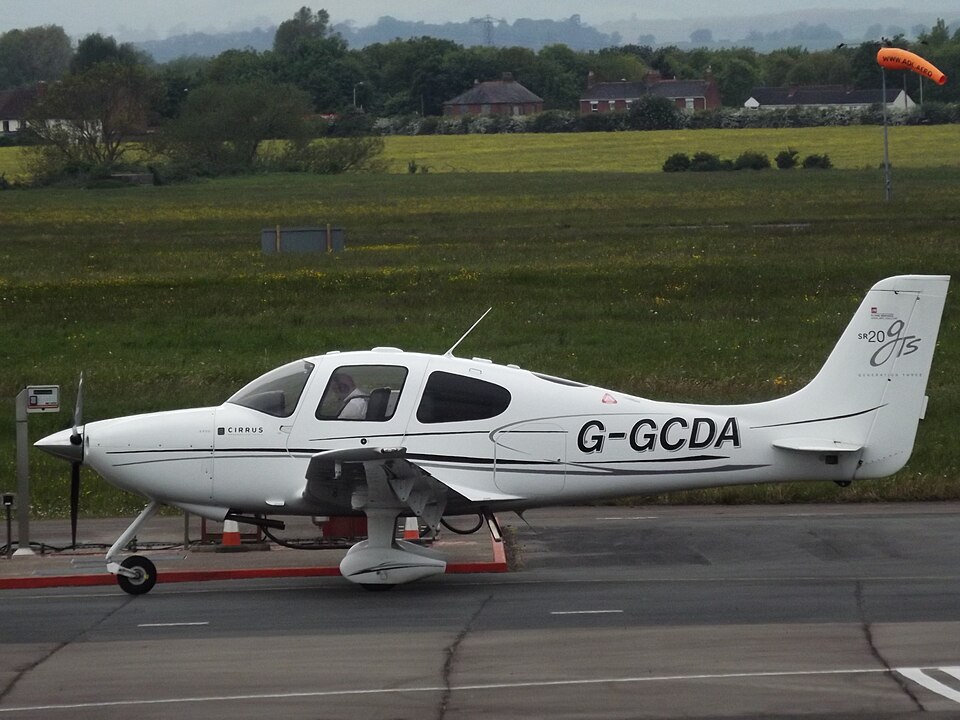
The Cirrus SR20 is fitted with two batteries to support the avionics system in normal and emergency situations. The aircraft is equipped with a ballistic parachute recovery system (CAPS). In the subject aircraft, the CAPS had been modified to be electrically initiated. A diode was introduced as an integral part of the battery relay with the CAPS modification to suppress voltage spikes on relay switch-over. When the relay manufacturer stopped including the diode within the relay, an external diode was introduced, consisting of a heat-shrink insulated diode with two spade connectors across the relay terminals. The aircraft circuit diagrams were updated accordingly during the modification programme.
Discussion
During recent maintenance, the No 2 battery relay was replaced to rectify a battery charging problem. Subsequent investigations suggested that a fault with the diode may have been the cause of the relay failure. It is also possible that disturbance during the relay replacement could have led to a short within the diode. Examination of the diode showed evidence of overheating, but it is not clear exactly how or when the diode failed. Nevertheless, it appears to have allowed the No 2 battery load to pass through the relay coil and through the aircraft wiring to the circuit board track connecting the system to the bat 2 switch. The circuit track was not designed to sustain an electrical load of this magnitude and subsequently overheated. The awkward location and unremarkable look of the diode assembly meant its significance could easily be overlooked.
Actions by the Manufacturer
The aircraft manufacturer examined the switch panel circuit and reviewed the sequence of events. They understood the position and unremarkable look of the diode and identified a slight risk of mis-assembly. To address this risk and inform owners, they released an update to the parts catalogue, wiring manual, and electric CAPS service bulletins. They added a fuse to the harness assembly to prevent damage; engineering drawings for this are released and will be used in new aircraft. Issuing new CAPS kits is planned but not yet released. Adding the fused harness will require additional revisions for the service bulletins. The fused harness is field retrofittable and can be installed in existing aircraft and listed as the field spare.